Gas Furnace Troubleshooting
It's the time of year when heating and air conditioning companies start refamiliarizing themselves with the operation of common home heating systems, which include:
Gas furnaces
Natural gas
Propane
Heat pumps
Electric furnaces
Oil heating
This article focuses on the operation and common problems that homeowners with gas furnaces may face.
General Procedures for Troubleshooting a gas furnace
All troubleshooting starts with identifying the common categories of complaints or problems, then the possible problems in the system, followed by the symptoms and causes of specific problems. Causes can be electrical or mechanical and related to the use of gas appliances.
The common categories of complaints or problems:
Entire system operation
Unit operation
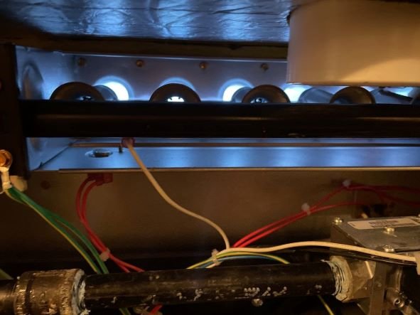
Burner operation
Heat exchanger
Cost of operation
Noise
Gas Furnace Diagnostic Flow Charts
Many technicians utilize a furnace troubleshooting flowchart.
The first thing you always check is the power supply. Is power being supplied to the unit? A voltmeter is a handy tool to use in checking the power supply.
The second item to check is the thermostat. Is the thermostat calling for heat? If both of these conditions are satisfactory, the wiring diagram should be referenced.
Before cycling power or removing a door that would de-energize the unit, inspect the furnace for the presence of a fault light. This is invaluable information that gives the technician insight into the cause of a shutdown or fault. Many times, cycling power will cause this valuable data to be lost.
Gas Heating System Problems
Many of the solutions to problems are not always evident when the cause is determined. The following list of problem categories includes additional information regarding some of the remedies that can be tried.
The control transformer burned out
Improper heat anticipator setting
Improper burner adjustment
Improper combustion air supply
Improper venting
Blower motor
Expansion noise in heat exchanger
The control transformer burned out
An ohmmeter should be used to determine whether the primary or the secondary winding of the transformer is burned out. The cause is probably an overload in the secondary, which needs to be corrected before the transformer is replaced. If the overload cannot be reduced, a larger transformer must be used for the replacement.
Pilot outage

One of the most common causes of pilot failure is improper impingement of the flame on the thermocouple. Sometimes the pilot is extinguished by the burner during lighting. It is blown out by the burner flame. To correct this, it is often necessary to reposition the pilot to a more favorable location.
Gas valve stuck open or closed
A malfunctioning gas valve should be replaced never repaired.
Improper heat anticipator setting
The anticipator should be set at the amount of current traveling in the control circuit when the unit is operating. The current can be measured using a multiplier coil and a clamp-on ammeter.
Cycling on the limit control
Occasionally, a limit control will weaken and lower the operating range of the control. The normal range is to cut off between 140F for a counterflow unit to 160-220F on upright and horizontal units. If the control is cycling at a lower range, replace it.
Fan control settings
Almost all gas-fired units operate best with fan control settings of 125-130F fan on and 100-105F fan off. If the unit blows cold air on start-up, the fan-on temperature can be changed to 145-150F.
Improper burner adjustment
A properly adjusted burner will have approximately 40 percent of the combustion air mixing with 100 percent of the gas in the burner and 60 percent of the air mixing with the flame above the burner to complete the combustion process.
The proper setting for the primary air quantity is the beginning step in producing high unit operating efficiency. Improper setting of the primary air shutter can contribute to pilot outage by producing extinction flashback, called extinction pop.
As the gas is emitted from the orifice, it expands and hits the proper place in the throat of the burner venturi. This produces maximum pull of primary air into the burner. Setting the burner for the correct flame condition will mean a minimum opening in the primary air control.
An all-blue sharp flame is receiving too much primary air. This means that there is less radiant heat to heat the lower portion of the heat exchanger. Also, the excess air drives the flame products from the heat exchanger before a good transfer of heat occurs from the flue product to the heat exchanger. Flue product temperatures rise and the unit efficiency drops.
On the contrary, if the primary air is reduced too much, heavy yellow tips of improper burning carbon are produced. These result in much lower temperatures, and less heat is produced. Therefore, the unit efficiency will drop. In addition, the carbon will be released from the flame and collected in the heat exchanger, causing sooting and plugging of the flue passages.
When the burner is operating, the gas/air mixture is blowing upward through the burner port at a given speed or velocity (determined by the burner design and type of gas). There is also a downward force or burning velocity, which is equalized by the gas/air outward velocity when burning is taking place.
If, however, the burning velocity were to increase due to the shutoff of the gas supply, the flame could approach the burner. Either the burner would absorb the heat below the combustion point and extinguish the flame or the flame would burn down through the burner port and ignite the mixture in the burner. This ignition produces the extinction pop.
Improper combustion air supply
Excess air is needed for proper combustion, even though changes in gas pressure, heat content of the gas, and barometric pressure may occur. Draft conditions also change with barometric pressure and wind conditions.
When a unit encounters insufficient combustion air, the flame tends to become lazy and erratic and may even roll over the edge of the burner and out the burner pouch opening. The flame will seek air.
Improper venting
The mixture of gas and air produces a mixture of water, carbon dioxide, nitrogen, and excess air. All of this has to be removed from the exchanger. This removal process is called venting.
There are two types of venting: active (power) venting and atmospheric, or passive (gravity), venting. Active venting uses a mechanical device such as a motor-driven blower to either draw flue products from the heat exchanger or force combustion air into the heat exchanger.
The most popular type is the draw-type, where the blower is mounted on the flue outlet and creates negative pressure in the outlet of the heat exchanger to get the desired combustion efficiency. Because the pressure difference is caused by mechanical power, wind and/or atmospheric conditions have little effect on the venting performance.
In atmospheric, or passive, venting, hot flue gases pass from the heat exchanger into a flue pipe, chimney, or vent stack. The driving force for a passive vent is obtained from the hot gases rising in the surrounding cooler air. The amount of force depends on the temperature of the hot gases and the height of the gravity vent. The hotter the gases and/or the higher the vent, the greater the amount of driving force or pull that is produced. Also, the greater the pull, the more secondary air is drawn through the heat exchanger.
Enough air must be drawn through to provide complete combustion as well as complete venting of the flue products. If too much air is drawn out of the heat exchanger before the correct amount of heat extraction is done, this results in higher flue temperatures and reduced unit efficiency.
If the passive vent pipe were connected directly to the flue outlet, the amount of air drawn through the heat exchanger would vary with factors like the pull of the vent stack, the wind effect on the vent stack, and outside temperature.
Control of the venting rate on the heat exchanger would be impossible. Further, under some atmospheric conditions it may be possible to have a higher pressure at the outlet of the vent than the combustion process can overcome. This can produce poor combustion, with the production of carbon monoxide as well as the usual products of CO2 and H2O.
To overcome the effect of atmospheric conditions, all units use an opening in the venting system called a draft diverter. These all consist of an opening from the flue outlet of the heating unit, an opening into the vent pipe, and a relief opening to the surrounding atmosphere.
The mixture of flue products and surrounding air (called dilution air) that blows up the vent is called vent gas. The action of the draft diverter is to break the effect of the vent by introducing surrounding air and neutralizing the pull at the flue outlet. The heat exchanger then operates at approximately equal pressure from the burner opening to the flue outlet. The amount of air for combustion is then controlled by the flue restrictors.
If the conditions surrounding the vent stack increase the stack pull, additional air is drawn into the draft diverter to compensate for the increased pull. There is little effect on the heat exchanger's performance.
Under conditions where the vent stack pull is reduced or even reversed, creating a downdraft, all combustion flue products are forced into the surrounding area. In addition, the increased pressure in the flue outlet will reduce the flow through the heat exchanger. This can cause incomplete combustion and produce odors carried by the gases and moisture produced by the combustion process.
Even though no odors may result, the large amount of moisture produced in the combustion process can accumulate in the occupied area and create adverse living conditions or possible structural damage.
To check for proper operation of the vent system, use a candle placed below the bottom edge of the diverter opening. With the unit operating and up to temperature, the candle flame should bend in the direction of the opening in the diverter. If the flame is neutral, the draft is on the weak side. Possibly the vent stack is not high enough or large enough. If the candle flame bends outward, a draft problem exists that must be corrected. If the vent stack cannot be lengthened or enlarged, a forced-draft unit must be installed to overcome the problem.
Furnace Blower Motor drive
Belt-driven blowers have a higher probability of vibration problems than direct-drive blowers due to the additional parts involved. The most common problem is due to belt tension. It is commonly believed that the tighter the belt, the better the performance, but the opposite is true.
The tighter the belt, the harder the motor has to work to get the belt in and out of the pulleys. They should therefore be as loose as possible without slipping on startup. It should be possible to easily depress the belt midway between the motor shaft and blower shafts ¾ into 1 in for each 12 distance between the shafts.
Alignment of the motor and blower pulleys is important to keep vibration to a minimum as well as to reduce wear on the sides of the belt. Both the motor pulley and blower pulley should be checked. They should be parallel to each other and perpendicular to the shaft. A warped pulley has a visible wobble that will create vibrations. Warped pulleys should be replaced.
Abnormal noises coming from your furnace
Expansion noise in heat exchanger
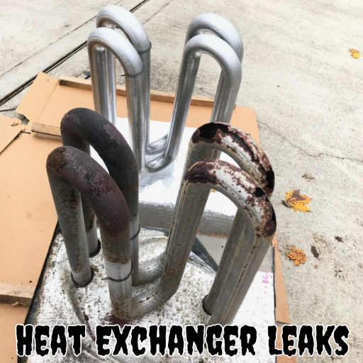
Some heat exchangers are composed of a right-hand and left-hand drawn steel "clamshell” welded together. The sections are then joined and welded into an assembly by fastening them to the front mounting plate and rear retainer strap. Sometimes in the welding process stresses will be set up if the two metals are at different temperatures when the bond is made.
This results in expansion noises, ticking, and popping as the heat exchanger heats and cools. Most of the time, these noises are muffled by the unit casing and duct system to a level where they are not objectionable.
In extreme cases, it is possible to reduce the noise by operating the unit with the blower disconnected, allowing the limit control to turn the unit off and on. This should be done through several cycles of limit control.
Cycling on this extreme heat will cause the metal to stretch beyond the normal operation range and eliminate the sound. If this does not produce satisfactory results, the only cure is to change the heat exchanger.
Oil-can effect
This effect is caused by the sudden movement of a flat metal surface where a forming stress has been left on the surface. This stress causes the metal to have a slightly concave or convex position rather than a flat plane surface.
Temperature change will cause a stress increase in the material until the metal rapidly changes position to the opposite of its original position. This change will produce a loud bang. Ductwork is very prone to this action and must be cross-broken, it is subject to the oil-can effect. The best correction is to remove the panel and cross-break it to relieve temperature stresses.
What a homeowner can do
Check your thermostat settings
Verify your thermostat is set for heating and that the temperature setting is set to the desired temperature.
Check the program settings. Smart thermostats may have additional settings that aren't typical for most homeowners. You may consult the thermostat user guide or call customer support to ensure you understand the settings.
Make sure there is power to the furnace
If the thermostat is set properly, verify there is electrical power to the HVAC system.
Check the circuit breaker, and make sure it is "on" and not tripped. Check the furnace power switch. The furnace switch will be located near the furnace. It will look like a common household light switch. It's very often confused for the attic light.
If these are in the correct position, do not cycle power to the furnace. Furnaces have an indicating light that shows what caused the furnace to shut down. It is a flashing light visible through the sight glass on the furnace cover. Be aware that removing the furnace cover could also reset the furnace.
Check the air filter
A dirty filter is the leading cause of furnace problems. The furnace filter should be changed monthly. A clogged filter limits airflow and could cause the furnace to overheat.
Call a furnace repair technician
Gas furnaces are safe appliances and are highly recommended in nearly every home. However, poor repair or maintenance practices can very easily remove the safety margin designed into every furnace.
Your furnace has several safety features that shut down the furnace when a problem occurs. This includes:
Limit switch
Temperature sensors
Pressure sensors
Flame roll-out
Door safety
Flame sensor
If you have a furnace problem, never attempt furnace repairs or "just make it work". This can lead to a dangerous situation.
Cold winter weather is coming soon. Fall is a great time to make sure your furnace is working properly with a safety inspection. You want to be ready for the heating season.