Furnace Gas Valve
Complete Guide to Furnace Gas Valve Design, Operation, and Replacement
Everything you need to know about a furnace gas valve in one place.
Typical replacement costs for furnace gas valve
Gas valve prices vary by manufacturer and type. Basic single-stage gas valves cost between $100-250. Two-stage and modulating gas valves cost significantly more. Gas valve pressure should be tested following a furnace gas valve replacement. A soap bubble test should be performed to verify there is no gas leak. You can expect to pay $150-250 in labor costs.
How much to replace a faulty furnace gas valve?
Single-stage faulty gas valve replacement will cost $250-500.
Combination Furnace Gas Valves
In times past, a combination of controls consisting of a pressure regulator, a solenoid valve, and a pilot safety valve was used to supply gas to a heating system. Today, these controls are combined into a single valve assembly called a combination furnace gas valve. In this article, we will also discuss basics of how a furnace gas valve works.
Functions of a combination gas valve:
Manual control for ignition and normal operation
Pilot supply, adjustment, and safety shutoff
Pressure regulation of burner gas feed
On/off main gas valves controlled by the room thermostat
Main Furnace Gas Valves
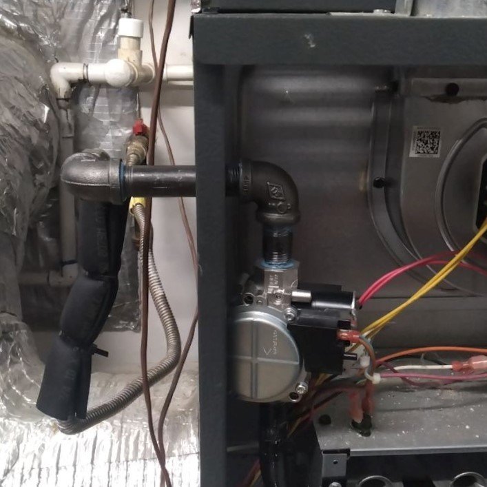
The main furnace gas valve is used to control gas flow to the burners. The valve has four main parts:
Valve body
Seat
Disk
Stem
When a furnace gas valve opens, the disk is lifted off the valve seat and gas flows through the valve. Gas valves can be classified as either direct acting or pilot operated.
A direct-acting valve is a valve where the mechanism that gets energized is the same device that opens the valve mechanically. Examples of direct-acting valves:
Solenoid
Bimetal
Heat motor valves
Diaphragm valves are pilot acting. The diaphragm is what moves the stem to open and close the valve. Diaphragm movement is caused by a pressure difference. Pressure to the diaphragm is controlled by a small valve called an operator.
Direct-acting pilot control valves
Solenoid valve

The most common type of direct-acting valve is the solenoid valve. Most solenoid valves are normally closed but can also be normally open. When the coil in a normally closed valve is energized, magnetism lifts the stem and valve disk off the valve seat and the furnace gas valve opens. When de-energized, the weight of the stem or spring pressure forces the stem and valve disk down, reseating the disk.
Solenoid valves are quick acting. This can cause problems. Some burners work better if the natural gas pressure increases gradually. To help with this problem, some solenoids have springs and fluid to slow down the stem.
Bimetal Valve
Bimetal valves are slow opening. A change in temperature causes the operator to warp lifting the disk off of the seat. This temperature change is caused by a heater. The valve is open and closed by turning the heater on and off. Bimetal valves close slowly because the bimetal must cool before closing the valve.
Heat motor valve
Heat motor valves operate on much of the same principle as bimetal valves. The heat from an electric heater is used to control the opening and closing of the valve. The difference is they use an expansible rod instead of a bimetal. An expansible rod is a rod inside a sealed cylinder that is filled with fluid.
Heating the cylinder causes the fluid to expand and push the rod out. This pushes down on the stem, unseating the valve. Heat motor valves are reverse seated which is why pushing down the stem opens the valve. Then the valve is closed by spring pressure while the expansible rod cools.
Gas Furnace Diaphragm Valves
Today's gas furnaces use pilot-acting diaphragm valves. Pilot valves control pressure to the underside of a diaphragm, causing the diaphragm to raise or lower. The pilot valves can be solenoid, bimetal, or heat motor operated.
Furnace Gas Valve Operation

The pilot valve controls a bleed port, which creates a pressure difference across the diaphragm opening and closing the diaphragm. Underneath the diaphragm, the incoming pressure pushes up, opening the valve.
The diaphragm lifts due to the pressure beneath it and lets gas flow through the valve. When the pilot is de-energized, the bleed chamber is closed to the valve outlet and opened to the gas inlet. The bleed chamber pressure climbs to the incoming pressure and forces the diaphragm down, closing the valve.
High-efficiency furnace gas valves
Today's furnaces achieve improved efficiency by regulating gas flow through multi or variable staged gas valve operation.
Two-Stage Furnace Gas Valve

Two-stage gas valves have two positions: The first position maintains a lower manifold pressure, and the second provides a higher manifold pressure. The lower pressure of the first stage allows the furnace to run longer in mild weather. This raises system efficiency by limiting startup and shutdown losses. Two-stage gas valves can be operated with a standing pilot light, intermittent pilot, direct-spark ignition, or a hot surface ignition system.
Two-Stage Gas Valve Operation
Two-stage valves have two regulators and two solenoid operators to provide two distinct stages of pressure. When the first stage pressure is actuated, its pressure is applied to the top of the diaphragm opening the valve. When the second stage is needed, the regulator opens allowing higher pressure to be applied to the top of the diaphragm opening the valve further.
Two-stage gas valve settings
The first-stage setting is a percentage of the full output of the valve. On some valves, both the low and high regulators are adjusted separately. The high-pressure regulator adjustment is always set to be less than the low-pressure adjustment. The first-stage solenoid must always energize before the second stage.
Modulating Furnace Gas Valve
Modulating furnaces are used in communicating control systems. The gas flow and airflow must be matched to provide the proper firing rate. The furnace will operate at 40-100% output.
Modulating furnace gas valve operation
The controller senses the supply- and return-air temperatures to sense temperature rise. The controller then proportionally adjusts the thermostat input, the modulating gas valve, and the variable-speed ECM blower to maintain the proper firing rate and air-discharge temperature. Some systems can take other variables into account, such as gas heating values and air density.
Checking and Adjusting Furnace Gas Manifold Pressure

Furnace gas pressure should be checked following a furnace gas valve replacement or any major gas system repair. Furnace operation should not be checked by just seeing blue flames. That is just like checking the charge of an air conditioning system by feeling the suction line.
Anyone can put their hand on a register and say it's blowing hot or cold. HVAC technicians are expected to be able to confirm a system is running as designed using precision measuring instruments and calculations.
Incorrect pressure can lower the system operating efficiency and increase the operating cost. Under-fired furnaces will lose capacity while over-fired furnaces can be a safety risk due to increased CO output. When adjusting, always set the pressure according to the manufacturer’s specifications. Common pressures are 3 to 3.5 inches of water column for natural gas furnaces and 10.5 to 11 inches of water column for LP gas furnaces.
Measuring gas pressure
A manometer rather than a typical pressure gauge must be used to measure this very low pressure which is far below 1 psi. Several different types of manometers may be used. The simplest and cheapest is a water tube manometer.
Portable Magnehelic gauges may be used, however, some types may not read high enough on the scale for LP gas. Digital manometers although considerably more expensive are convenient and accurate. A bonus is that you can also use most digital manometers to read duct pressures—so the tool can serve more than one function.
Checking supply pressure
Before checking the pressure on the furnace, you should initially perform an incoming gas supply line pressure check. First, familiarize yourself with the gas valve and locate the pressure taps on the inlet and outlet sides of the valve as well as any pressure adjusting screws on the valve regulator.
Typically, a pressure rating will be stamped on the valve body and the required incoming pressure will be listed on the appliance rating plate. The first step in checking the incoming gas line supply pressure is to secure the electrical power to the furnace and close the manual gas shutoff valve located in the gas supply line just ahead of the furnace. Once the plug for the inlet side pressure tap has been removed, you may need to screw in a barbed fitting to hook up the manometer tubing. If you are using a digital manometer, it should be zeroed per the manufacturer’s specifications.
When the manometer is in place, the manual gas valve may be opened and incoming pressure should now be indicated. The furnace may now be started to determine any line pressure drop. All other gas-fired appliances on the same incoming line should also be started and operated during the pressure check. This ensures that there is an adequate gas supply for the maximum demand condition.
After the check is complete, secure the electrical power to the furnace and close the manual valve. Remove the instrument and replace the inlet side pressure tap plug. If the measured supply is within the furnace design limit, then you may proceed with a pressure check.
Gas manifold pressure check
To begin the gas manifold pressure check, secure the electrical power to the unit and close the manual gas valve located in the gas supply line just ahead of the furnace, if not already done. Remove the plug for the outlet side pressure tap on the gas valve and screw in a barbed fitting to hook up the manometer tubing if required. When the manometer is in place, the manual gas valve may be opened and the furnace started.
Adjusting gas pressure
The adjusting screw will often have a cap or slotted cover that must be removed before an adjustment can be made. Generally, the pressure can be increased by turning the adjusting screw clockwise and decreased by turning the adjusting screw counterclockwise.
Always adjust the regulator to provide the correct pressure according to the original equipment manufacturer’s specifications listed on the appliance rating plate.
After the gas manifold pressure has been properly set, the cover for the adjusting screw should be put into place while the manometer is still attached. This allows you to check that tightening the cover did not slightly change the setting.
Once all proper operating conditions appear normal, the unit can be shut down, the electrical power secured, and the manual gas valve closed. Then you can safely remove the manometer and replace the outlet side pressure tap plug. The furnace can now be made ready for normal operation.
Checking for gas leaks
Anytime work is performed on a natural gas or propane gas furnace, the system should be checked for gas leaks. This test can be done using an electronic gas sniffer or soap bubbles.
Summary
Furnace gas valve replacement is a common heating repair. You should never attempt to repair a furnace gas valve. Replacement should always be performed by a licensed and insured HVAC contractor. Improper work and testing will cause your system to malfunction. But not only that, gas leaks can be dangerous to your home and family.
Proper operation of your furnace and entire heating system should be checked annually for safety and efficiency. A heat exchanger crack can be dangerous to residents.